
Service is a Factor
In Part 1, we looked at a simple variable speed (frequency) driven (VFD) motor output chart contrasted with a centrifugal pump duty point. The primary lesson was matching the pump power demand with the motor capability at a given speed. In this entry, we’ll dig a little deeper into the motor side.
The rotational speed of an AC motor is dependent on the number of magnetic poles it was designed with (which is a fixed value such as 2, 4, 6, etc) and the electrical frequency (50 Hz, 60Hz, etc). The equation for determining synchronous speed is:
![]()
As you can see from the table below, there are significant speed gaps between the synchronous speeds. It may be desirable to run a centrifugal at its most efficient point between these speeds, even with a trimmed impeller.
| Number of Poles | Synchronous Speed at 60Hz | Synchronous Speed at 50Hz |
| 2 | 3,600 | 3,000 |
| 4 | 1,800 | 1,500 |
| 6 | 1,200 | 1,000 |
| 8 | 900 | 750 |
| 10 | 720 | 600 |
Therefore, in order to change the speed of the motor you must change the electrical frequency, which is fixed on the electrical grid. This is where VFDs come into play, as they take the fixed input frequency and permit a variable output frequency to the motor.
Three phase AC electric motors are nominally designed to be powered by a sine wave signal as shown below, as provided by the electrical grid (direct on-line connection):
Synchronous Speed
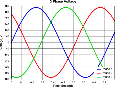
Notice the harmonious and smooth nature of the pure sine wave from the grid. Modern microprocessor controlled VFDs unfortunately can not generate a natural sine wave. Instead, they typically rely on simulating a sine wave using Pulse Width Modulation (PWM), which looks like this:
Variable Speed
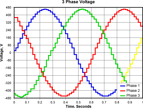
The resolution of the jagged steps in the simulated sine wave is a function of the resolution or PWM frequency setting. These relatively sudden voltage spikes and the resulting harmonics can break down the motor insulation and increase heat inside the motor.
NEMA motors are often nameplated with a service factor of 1.15, meaning that the motor can continuously supply 115% of rated power and operate within the stated temperature rise. Conversely, IEC motors are rated with no service factor. However, unless the nameplate explicitly indicates VFD rated, the stated values are based upon a natural sine wave.
When power is supplied from a VFD, the service factor is lost or decreased in order to maintain the nameplate temperature rise.
So when sizing a VFD for your centrifugal pump application, beware relying on the service factor. Also, don’t overlook elevation limits, belt losses and transient conditions.