
Wilfley Kpro®, K, and HD slurry pumps are very commonly used in lime slurry applications. Their unique design makes them almost perfect for this duty, but care must be taken in the inlet design to ensure proper operation. Kpro®, K, and HD are all designed with their suction on the side of the pump, and with the impeller facing the motor, so that the pump shaft runs through the eye of the impeller. The Wilfley Dynamic Expeller Seal is located on the shaft just adjacent to the eye of the impeller. See the image provided below.
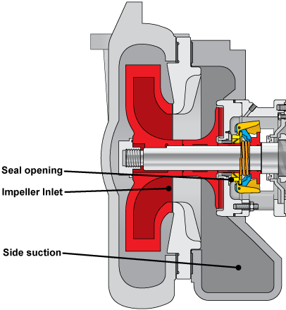
While the pump is running, the Dynamic Expeller Seal opens to the atmosphere, allowing the liquid interface to form around the seal. Due to the close proximity of the impeller eye to the Dynamic Expeller Seal, pressure is equalized between the inside and the outside of the case. This creates the situation where a Kpro®, K, and HD cannot create suction pressure, and are entirely dependent on gravity to supply flow into the inlet of the pump. Obstructions, elbows, long lengths of suction line, and plugging in the suction line are very detrimental to the function of these pumps. Wilfley Kpro®, K, and HD slurry pumps that have extended suction lines between the feed tank and the pump, or contain restrictive elements in the line, such as isolation valves, transitions, etc., will result in low inlet pressure to the pump, choking the pump and preventing it from producing full flow. If the pump is producing significantly lower flow than it’s rating would indicate, it is usually an issue with the inlet design, rather than the pump itself.
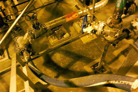
The inlet line above transitioned from steel to rubber flexible hose and back to steel, going through two elbows and two isolation valves, stretching over 30 feet. The resulting flow from the pump was approximately 30 gpm. The pump was rated for 165 gpm. This customer was lucky; the pump only produced about 20% of the rated flow, but was in good condition and continued to operate.
This customer was not as lucky:
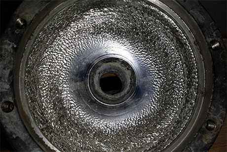
This is the inside of the case of an end-suction pump with a lengthy inlet line in a lime slurry application. End-suction pumps do generate suction pressure, so low inlet pressure commonly leads to cavitation such as seen here. Cavitation will quickly destroy the pump, wearing away at the impeller and case, causing bearing problems, etc. Wilfley Kpro®, K, and HD slurry pumps are much more forgiving of improper inlet designs than any other pumps available.
Inlet Design
Hydraulic Institute 12.1-12.6-2005 deals with the design and operation of centrifugal slurry pumps. Section 12.4.9 Piping System Design states, “Good slurry sump design should be aimed at preventing uneven flow into the pump suction while providing for transportation of pumped solids to the pump suction. …The main geometrical principle is to minimize horizontal surfaces in the structure anywhere but directly under the pump suction, thereby directing all solids to a location where they may be transferred by the pumping equipment. Vertical or steeply sloped (at least 45 degrees above horizontal) sides shall be provided for the transition from upstream conduits or channels to the tank outlet to the pump. This will greatly reduce the chance of solids settling and sloughing into the pump causing severe surging and reduced pump wear life.”
Hydraulic Institute also recommends the suction line not being longer than 10 pipe diameters. For a 4-inch inlet, that translates to 3.33 ft.
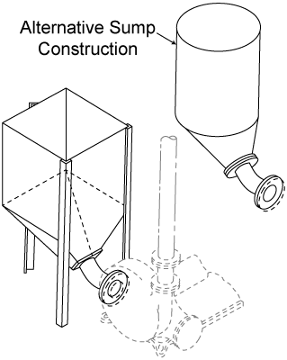
Intake Sump
Wilfley recommends feeding the pump by means of sump tank or feed box placed as close to the pump as possible. When the feed to the pump is increased or decreased, the material in the sump simply seeks a higher or lower level, respectively. Hopper bottom sumps are much more satisfactory than flat bottom sumps. A sloping pipe from the intake sump into the pump is particularly desirable when handling materials that settle quickly, such as lime, or when the quantity is small for the size of the intake pipe and pump. Long suction pipes require sufficient velocity in the pipe to prevent setting. In practice, the minimum velocity required to prevent lime from settling varies from 3 ft/sec to 6 ft/sec, depending on concentration and particle size. Contact Wilfley for recommended sump dimensions for your specific application.
Inlet Design Hints
- Design the inlet piping to be as short as possible between the sump and pump.
- Maintain the inlet line in as straight a run of piping as possible. Every change of direction adds friction losses to the flow. A straight line from tank to pump is preferred.
- Minimize transitions. A single piece of pipe connected to the outlet line from the tank running straight to the isolation valve just prior to entering the pump is ideal. Every additional valve, connection point, or change in piping adds friction losses.
- Use piping one size larger than the inlet. For example, where inlet diameter of the Kpro® pump is 4 inches, use a 6 inch inlet pipe necked down to 4 inches at the connection point for best results.
- Consider the inlet head which provides flow velocity to the pump inlet. Set the fill level in the feed tank and the overall height of the tank so that the inlet head seen by the pump is high enough to provide adequate flow.
- Please note that too high an inlet head can cause sealing issues with the Dynamic Expeller Seal. Wilfley can assist with determining an appropriate maximum allowable inlet head for a given Kpro®, K, or HD slurry pump.